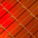
Each printed circuit board is manufactured via two crucial stages: inspection and test, which provide a thorough assessment of the finished product’s quality. Even if designers adhere to all guidelines and recommendations, mistakes, defects, or human error are always a possibility. To guarantee the performance, functionality, and dependability of the product, it is essential that these problems are found and fixed before the PCB enters the final development stage. Present-day technology allows for the direct execution of completely automatic printed circuit board testing in the same production environment as the PCB. The three primary methods now in use are X-ray inspection, optical examination with cameras, and functional testing. After completing the assembly step, with all components correctly positioned and soldered, the printed circuit board may also be tested. Optical inspection examines the printed circuit board (PCB) in search of any soldering issues such bridges, short circuits, or subpar electrical connections. These systems make use of mobile high-resolution cameras that can frequently find even poorly positioned or missing parts. Some test methods also include three-dimensional X-ray examination, which can find issues that are invisible to ordinary optical inspection. For instance, X-ray equipment may spot flaws in the soldering underlying flip chips and Ball Grid Array (BGA) integrated circuits (an example of a flip chip package is shown in Figure 1).

Automatic optical inspection
With a resolution of up to a few m, automatic optical inspection, also known as AOI, uses the optical signal detected by a single camera (2D vision) or by many cameras (3D vision) to check flaws in printed circuit boards. Only printed circuit boards with optically controlled soldering, connections, pads, and traces may use this technology to obtain results that are reliable. The early detection of assembly issues including shorts, open circuits, thin solder, scratches on traces, and more is also made possible by the AOI approach. The model board, sometimes referred to as the “golden board,” or an image database including good and faulty boards are compared to the high quality photos captured by 2D/3D cameras. All inspections that would usually need to be completed manually may now be carried out totally automatically, accurately, and quickly using the AOI approach. Additionally, following the assembly process, it is feasible to determine the components’ accurate location along the vertical axis and on the PCB plane (the AOI 3D technique allows also to detect the height of the components). The benefit of AOI is that it may be installed right at the end of the PCB production process, thereby catching potential flaws earlier. Being a passive approach, it can only find faults that are on the surface of the PCB.
X-Ray inspection
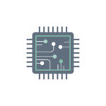
AXI (Automatic X-Ray Inspection) technology finds PCB flaws that are not apparent to the unaided eye or using an AOI optical system, in contrast to conventional inspection techniques. In reality, X-rays can see through both the PCB layers and the component packaging, producing incredibly detailed 2D or 3D pictures. This enables, for example, the identification of soldering problems on buried pads or Ball Grid Arrays (BGAs). It is sometimes adequate to undertake the X-ray inspection of only the components that have non-visible pads when making small batches of PCBs or during the prototype process. Although this method provides the finest outcomes, AXI is a lengthy and expensive procedure that requires highly educated workers. This justifies its applicability to PCBs created on a big scale or to applications that are extremely important and complex. This method provides good results for BGA components (an example is shown in Figure 2) and enables the inspection of any concealed solder points between the component and the PCB surface.

Inspection with infrared rays
Thermography, another name for infrared inspection of printed circuit boards, makes use of the heat that the PCB and its components release. This method is very useful in power applications since there are larger currents at play. With the use of specialized thermal cameras (like FLIR), infrared examination can yield data that optical inspections cannot. An infrared camera may detect an increase in temperature as a result of certain PCB flaws, such as poor soldering, which can increase electrical resistance at certain spots on the circuit. Image subtraction is a typical thermography technique. Before turning on the device, the right software takes a picture to create an optimum thermal profile. The static temperature values that were reflected in this reference image are then removed from the succeeding photos that were taken after turning on the device, leaving just the actual temperature deltas caused by the heating of the board and its components. It is crucial to stress that PCB cloning without authorization or suspected counterfeiting can both be found using thermography and X-ray examination.
In-Circuit test
In-Circuit Testing, or ICT, is a completely automated test that may find manufacturing or assembly flaws in PCBs through a precise schematic verification procedure. This test accesses particular areas of the circuit by laying the PCB on a bed of nails and evaluates each component’s performance independently of all other components linked to it. The performance of some analog components, such op-amps, may be measured along with other parameters like resistance, capacitance, and impedance. A partial check is typically not cost-effective due to the complexity of some digital circuits, but it is still feasible to assess their behavior. The PCB may be thoroughly tested using the ICT approach to make sure that the circuit has been built appropriately. Shorts and open circuits, missing or misplaced components, soldering flaws, and other faults were discovered. Custom test masks may be made for big PCB batches to run ICT more rapidly and effectively. The high degree of defect coverage, which may approach 98%, is another benefit. The primary drawback of this method is its high cost, which is only acceptable for manufacturing on a big scale. Additionally, each PCB requires its own bed of nails, and it is possible to do the verification only at certain locations on the PCB that correspond to the test points specified by the designer.
Flying probe test
Compared to the in-circuit test, the flying probe test has the advantage of having a lower cost. This technique uses a mobile probe that is placed in contact, in a completely automatic and configurable way, with appropriate electrical points of interest present on the PCB. These points include component pins, vias, pads, and more. Compared to ICT, the flying probe test has the advantage of being able to test a large number of points on the PCB and not just the test points provided by the designer on the printed circuit board. Furthermore, a custom-made device is not required (such as the bed of nails) and any changes made to the components or to the original PCB design only require a software update. Thanks to the high number of points that can be verified, the flying probe test guarantees higher defect coverage than the ICT test. However, it is a much slower process which can become unacceptable for large-scale PCB production. Figure 3 shows equipment for automatic PCB testing with a flying probe.

Functional test
The functional test of a PCB is often carried out during the project’s final stage. It examines how the printed circuit board performs under various operating scenarios that are simulative on a bench. The functional test is frequently carried out to confirm certain customer-reported behaviors by putting the PCB under various electrical and environmental stresses. This test is being done to make sure the Device Under Test (DUT) is functioning as it should. The functional test can be as basic as a power supply test (power on/power off), all the way up to a comprehensive test with specialized communication protocols and testing software, depending on the complexity of the project and the requirements to be evaluated. Functional testing can be used in place of more expensive testing processes because of its flexibility. The functional test ensures that every board that leaves the production line is prepared for field operations by simulating the real operating environment accurately and providing immediate feedback on the project’s quality. For this reason, it is increasingly used in the production of small batches. Although it is a simple process that can be used on any type of PCB, the functional test only gives coverage for flaws that are directly related to the tests carried out when running the test. Additionally, if under extreme stress, a board that has passed functional testing may quickly fail.
Burn-in test
Before a PCB is used in the field, a burn-in test, which shares certain similarities with functional testing, evaluates its performance and searches for hidden flaws. The boards are put through harsh circumstances that go beyond the rated operational parameters during the burn-in testing. In order to foresee any problems that may develop during actual use, the objective is to identify potential failures early and test the device performance under excessive load. The burn-in test replicates intense operating circumstances that might precipitate prospective failures, in contrast to other inspection techniques that just look for signs of potential failures. Variations in temperature, voltage, current, operating frequency, or any other operating characteristics pertinent to the DUT are frequently included in these severe working situations. The test’s results give designers precise information they may utilize to pinpoint the source of faults and improve their design or production processes.