The titles Metallic PCB, Insulated Metal Substrate (IMS or IMPCB), Metal Core PCB (MCPCB), Aluminum Clad, Aluminum Base, and others are used to describe this group of printed circuit boards. All of these definitions pertain to the same sort of PCB, which has the same technological features and advantages while appearing to be distinct. Metallic PCBs, which have up to 10 times less thickness compared to conventional layouts and 5 to 10 times higher thermal conductivity than FR-4 epoxy glass-based PCBs, first and foremost offer improved heat dissipation. Metal PCBs may employ very thin copper layers because to the very effective thermal energy transfer, which lowers costs and solution thickness.
Metal printed circuit boards (PCBs) are made up of a copper film used for circuit lithography, a metal layer with a high heat dissipation capacity, and a dielectric layer with high thermal conductivity (and hence high dissipation). Aluminum and copper are the two materials that are most frequently used to fabricate metal layers, however stainless steel can also be utilised in some cases. Aluminum is outperformed by copper in terms of performance and electrical characteristics, but copper is more expensive. It is possible for the metal layer to be made wholly of metal or partly of fibreglass (FR-4). Due to its high manufacturing complexity, the multilayer form of metallic PCBs is less prevalent. Instead, they can be single-sided or double-sided. A multilayer MCPCB requires that the layers be arranged equally with regard to the inner metal layer; for instance, a PCB with 12 layers would position the metal layer in the middle of the stack-up, with 6 layers above and 6 layers below.
Power supply, power converters, LED lighting systems, and power circuits in automotive contexts are examples of common uses for metal PCBs because metal can transmit heat quickly by removing it from high-power components (headlights, lights, cooling, climate and more). In addition to providing effective thermal management, this kind of technology enables the lifespan of components (such as LEDs) to be increased, enhancing the circuit’s overall dependability.
Application and structure
Today, MCPCB technology is frequently utilised in applications where a lower operating temperature must be maintained. It was first developed in the 1960s for high power applications. The core of any metallic PCB, the dielectric insulation material, is created to have thermal conductivity substantially greater than FR-4 (usually between 1W/mK and 9W/mK), enabling effective heat disposal. The produced heat may be transferred quickly and efficiently due to the insulating layer’s thin thickness (the typical measurement is 100 m) and excellent thermal conductivity. 2W/mK is a typical thermal conductivity value for the dielectric layer, which is substantially greater than the FR-4’s value. The dielectric layer should be kept as thin as possible to get the optimum outcomes. In reality, this makes it possible to shorten the distance that heat must travel from its source to the metal layer, which is thermally many times more conductive than the dielectric substance.
Figure 1 depicts a traditional metallic PCB’s construction. A thin copper sheet serves as the top layer, on which traces will be engraved, much like on traditional printed circuit boards. This layer’s usual thickness ranges from 1 to 4 ounces, although it can potentially be thicker. The dielectric substance, which serves to electrically insulate the metal layer from the copper film while permitting quick heat transmission between the two layers, is seen as the innermost layer. Finally, we get to the metal layer, which is typically comprised of aluminium and ranges in thickness from 1mm to 3.2mm (the typical value is 1.6mm).

LED illumination, motor control in electric and hybrid vehicles, solid state relays, power supply, converters, voltage regulators, solar panels, and photovoltaic cells are some of the principal uses for metal PCBs. More broadly, this technology is appropriate for uses that demand a lot of energy and thus produce a lot of heat. It is preferable to utilise a metal PCB rather than a conventional FR-4 substrate if the PCB needs quick cooling. The most popular metal for the metal layer is aluminium, which has several beneficial electrical properties including great heat conductivity between 5W/mK and 2W/mK, high breakdown voltage (3kV and higher), and high tensile strength.
The Top 5 Benefits of MCPCBs
Metal PCBs provide superior capacitive coupling, increased power density, and strong electromagnetic shielding in addition to efficient heat dissipation. Thermal vias, which are used in conventional PCBs, can further enhance thermal performance. Here are the top five advantages of this technology.
1 – Thermal Dissipation
One PCB alternative with a better heat conductivity is MCPCBs. They avoid potential circuit damage and can manage high density circuits with greater power levels by keeping the heat as far away from the power components as feasible. One of the most popular materials for this kind of substrate is aluminium because, in addition to having good electrical qualities, it is also affordable and recyclable. Compared to PCBs constructed with FR-4, metal core PCBs transmit heat 8 to 9 times quicker. To establish the shortest path from the heat source to the supporting metal plate, the dielectric layer must be extremely thin. It typically has a thickness of between 0.003 and 0.006 inches. A test on an MCPCB with an integrated 1W LED, for instance, revealed that its temperature stayed very near to the ambient temperature of 25°C, although the same power LED installed on a FR-4 board attained a temperature that was 12°C higher than the ambient one.
2 – Increased Stability and Strength
Concerns concerning heat dissipation have been highlighted by the recent and rapid growth of LED technology, particularly with high power LED lights. The circuit may have stability and reliability issues as a result of these LEDs because they are often positioned directly on the PCB. Heat dissipation can impair the operation of electronics that use a lot of power if the proper approach is not used. This issue is successfully resolved in these applications by the use of metal PCBs. Aluminum gives strength and resistance to the printed circuit board without adding weight, and it also ensures a high level of longevity.
3 – Dimensional stability
As external circumstances change, the size of a printed circuit board made of metal will stay more stable than one made of a more conventional material, like FR-4. PCBs containing metal layers (such as aluminium) have had a relatively slight size fluctuation, ranging from 2.5% to 3.0%, when heated between 30°C to 150°C.
4 – Higher Recyclability and Lower Weight
PCBs with metal substrates are more conductive, more durable, and lighter than conventional PCBs constructed of epoxy materials. They are also more ecologically beneficial since the metals they employ, like aluminium, are non-toxic and simple to recycle. Aluminum is significantly less costly than other metals since it is fairly simple to mine and process. As a result, it is possible to lower the price of producing PCBs using substrates made of aluminium. A less expensive option to more expensive and large heat sinks is aluminium PCBs. Unbelievably, aluminium is a completely recyclable and non-toxic metal. Aluminum utilisation in metallic PBCs aids in protecting the environment along the supply chain from manufacturer to ultimate customer.
5 – Greater Lifetime
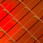
Compared to materials like ceramic and fibreglass that are frequently used in the production of PCBs, aluminium offers superior strength and longevity. It is a very strong metal that might lower the danger of unintentional breakage that can happen during different production phases, during assembly, or during typical usage of the finished product. Examples of aluminium PCBs used in LED lighting applications are shown in Figure 2.