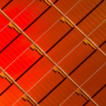
Each printed circuit needs physical supports, also known as substrates, on which to position the components and make the necessary connections between them, regardless of its nature (rigid, flexible, or rigid-flex). One of the first hurdles the designer must overcome on the way to creating a high-quality PCB is the kind and technical properties of the substrates used for PCB production. The PCB’s performance is directly impacted by the substrate’s kind and properties. A solid substrate, for instance, gives the PCB better strength and longevity, but a flexible substrate allows the engineers more design alternatives. Essentially nonconductive, the substrate is generally chosen based on the value of its dielectric constant (Dk). Substrates are composite dielectric structures consisting of glass or paper and epoxy resin. Substrates are occasionally enhanced with particular substances, such ceramic, to increase their dielectric constant. The emergence of a wide variety of substrates, from solid glass fiber to flexible polymers, is a direct result of the printed circuit board industry’s ongoing evolution. Fiberglass has traditionally been the most popular type of substrate since it is an affordable, extremely dependable material that offers a nice, sturdy foundation for the PCB. A multilayer PCB’s typical stackup is shown in Figure 1. Copper foils are used to create the two external sides and two inside layers (which can be used as ground planes, power supplies, or for the layout of the traces). Pre-preg is used to create the innermost layer (the core), whereas substrates are used to create the outer two layers.

Technical characteristics
High strength and dependability are required in the materials and substrates used in PCB production because they affect the proper operation and longevity of the electronic circuit. The following are the primary technical factors that affect a substrate’s quality:
- dielectric constant
- thermal conductivity
- thermal expansion coefficient
- maximum operating temperature (MOT)
- electrical insulation.
The ability of a substance to store electrons in an electric field is expressed by its dielectric constant, also known as electrical permittivity (symbol ). Due to the high voltages and currents that power electronics substrates are exposed to, which result in non-negligible electromagnetic fields, this property is essential. If the dielectric constant is too high, these intense electromagnetic fields might actually induce currents in nearby traces. To get the same capacitance value, substrates with a higher dielectric constant must be manufactured at greater thicknesses than substrates with a lower dielectric constant. Therefore, a substrate’s size and weight can be reduced by using materials with lower dielectric constants. A smaller circuit can also be produced by designers by reducing the space between traces on substrates with lower dielectric constant. A material’s capacity to transfer heat is measured by its thermal conductivity, which is often referred to as thermal resistance. Thermal conductivity, measured in watts per Kelvin meter (W/mK), describes how well a material transfers heat through its volume. Another important feature for substrates is their thermal conductivity, particularly if heat from high-power devices needs to be dissipated to a ground plane or heatsink. The performance of specific components may be negatively impacted by high temperatures around them if the thermal conductivity is too low. This could result in malfunction or damage. The ability of a material to vary in size in response to changes in temperature is measured by the coefficient of thermal expansion (CTE). A substrate with a high CTE will expand more than a substrate with a low CTE at the same temperature. In multilayer PCBs, the CTE of a substrate is crucial. In fact, when the PCB is exposed to temperature cycles, a detachment could form between the layers themselves if the substrates that make up the various layers have differing CTEs. The high CTE substrate can expand with a force larger than its mechanical strength when the temperature rises, which can lead to cracks, chips, or other mechanical damage. Above this temperature threshold, the substrate will be more likely to fail. A substrate’s maximum operating temperature (MOT) is the temperature value up to which it maintains the properties indicated by the manufacturer. The electrical insulation of a substrate indicates how poorly it conducts electricity, and the substrate manufacturer often specifies both the MOT value and the time during which this limit temperature may be maintained without producing harm. This characteristic, commonly referred to as bulk resistivity (BR), gauges how many electrons are transported through a substance. The better a substrate’s bulk resistivity, the less likely it is that floating currents will form inside the material. A substrate’s ability to insulate is solely based on its thickness. As a result, a substrate with a higher bulk resistivity will probably be thinner than a substrate with a lower bulk resistivity when there is equal total insulation.
Main types of substrate
The materials used to manufacture PCBs are crucial because they must have exceptional qualities and features, including temperature resistance, adhesion, tensile strength, flexibility, dielectric strength, and dielectric constant. The substrates’ construction materials have a direct impact on the PCB’s performance, dependability, and lifespan.
FR-2
The substrate type with the lowest performance is likely FR-2. In spite of being flame retardant (FR-2 stands for Flame Retardant Level 2), phenolic substance, which is a specific kind of impregnated paper put on top of a glass fiber, makes up FR-2. These days, only a few extremely cost-effective consumer applications—like tiny, affordable radios—use this substrate.
FR-4
It is the substance that is utilized to make PCB substrates the most frequently. It is made of a laminate sheet of epoxy with glass reinforcement. The epoxy resin used is FR-4, or Flame Retardant Level 4, and it is both water resistant and moisture-resistant. The electrical insulation, strength or weight ratio, and tensile strength are all extremely high. In addition to the above-mentioned general traits, there are many varieties of FR-4 that differ in some particular qualities, such as:
- Standard FR-4 has a heat resistance of between 140°C and 150°C, making it the most popular and affordable variety of FR-4
- High-temperature FR-4 (high Tg): This variant of FR-4 gives a high value for Tg (glass transition temperature), enabling the substrate to reach temperatures as high as 1180°C
- FR-4 halogen-free: This is a type of material with a negligibly low halogen concentration (which develop toxic substances during burning). One of the most often utilized fireproof materials is halogen.
PTFE (Teflon)
It is exclusively utilized in applications with high speed and high frequency communications since PTFE, a form of plastic, provides no resistance. Due to its exceptional flexibility and high level of insulation, PTFE is useful in applications requiring precise tolerances. Additionally, it has a high degree of mechanical strength, is flame-resistant, and retains its stable properties as the temperature changes. It is employed in electronic devices that handle signals from several hundred MHz to several tens of GHz because of its excellent high-frequency properties.
Metal materials
Aluminum-based metal substrates typically have strong dielectric and thermal characteristics and exhibit moderate expansion. Excellent high frequency performance is guaranteed by aluminum, which can easily resist temperatures of up to 350°C. The ceramic substrate, which is generated using an electrochemical technique that directly deposits an aluminum oxide crystal dielectric layer on the surface of an aluminum substrate, is electrically coupled to the aluminum substrate. This material provides greater dielectric heat conductivity than traditional dielectric materials currently used for PCBs because the thickness is significantly thinner than normal substrates. Although the aluminum substrate is more expensive than other options, it provides outstanding high frequency performance. It is utilized in RF equipment, wireless communication base stations, microwave equipment, and PCBs for LED lighting.
LTCC
Low Temperature Co-fired Ceramics, or LTCC, is an acronym for a particular kind of substrate that is frequently used in multilayer PCBs. Since the aluminum oxide used to make it must be burned at a high temperature (1500°C), layers containing traces formed of low melting copper cannot be simultaneously burned. Aluminum oxide can be mixed with glass-based substances to enable the burning of LTCC substrates at temperatures as high as 900°C. This enables simultaneous burning when using a copper or silver circuit configuration that has a low melting point. In high frequency RF modules, this kind of substrate is frequently employed.
Flexible substrate
The flexibility of the materials allows for easy piecing or availing in the desired shapes without jeopardizing the electrical continuity of the circuit in any way. This enables designers to create printed circuits that may be applied to smaller spaces or irregularly shaped components. These materials use specific types of plastic film in place of glass fiber or epoxied resins. The flimsy materials might be made of inexpensive materials like poliestere and PEN or more expensive materials like polyimide and LCP (polymer with liquid crystals). Due to their scarcity, flimsy substances require highly specialized equipment and labor, which raises their cost relative to other materials. Figure 2 displays an example of a PCB made with movable components.

The polymer polyimide, which is sometimes abbreviated as PI, has great thermal stability, thermal resistance, excellent electrical characteristics, and excellent chemical resistance. The majority of flexible PCBs on the market today are made of a polyimide material known as Kapton, which was developed by DuPont Corporation. Kapton has unique properties such a low dielectric constant of only 3.6, great heat resistance, and toughness.
Rigid-flex substrates
They are made by mixing substrates that are both flexible and hard. For instance, a PCB can include several polyimide layers adhered to a hard ceramic layer. In the medical, aerospace, aeronautical, and military industries, where severe criteria for dependability, robustness, mechanical resistance, and high temperatures are necessary, PCBs manufactured of this material are frequently employed in important applications.